RF Energy Concepts Sec. 101 Rev. August 21, 2007 ///
Home
Gravity Concepts
Create Momentum
New 2014 Grav. Constants
>
Light Speed vs Special Relativity
Force Interactions
RF Energy Concept
< RF Energy Concept <RF Energy_Iono. > Demo.s RF Energy > RF Energy Links >
< Prev Pg Contents Bottom \/ Next Pg >
Russian translation of this article by Genchi Info
Image via NRL
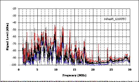
Fig. A1 Natural RF Radiant Energy Spectra of Ionosphere
Circa, Spring 1986 S. V. Byers
The Radio Frequency ( RF) Energy is demonstrated when a resonant radio frequency energy flow is established between two reflectors, and the broadband RF energy of the ionosphere maintains the resonant radio energy at a frequency determined by the natural conditions of the ionosphere.
A specific application of the RF resonance phenomenon is the creation of a resonant RF energy flow between the reflecting ionosphere and a tuned, resonant, vertically reflecting antenna system for the extraction of useful energy. The ionosphere provides two of the main functions. It provides the upper reflector and furnishes its random broadband RF energy to the radio frequency [ RF ] energy resonance. The resonance may be initiated by transmitters or natural pulses of cosmic or atmospheric energy.
The frequency of the resonance is preferably determined by the dominant echo frequency of the Ionospheric layer, and the matching tuned resonant frequency of the antenna system. From ionosounding test data the most likely frequencies for RF resonance, will be from 4.5 to 7 megahertz. The spectrum analyzer graph of the natural Ionospheric RF energy, Fig. A1, displayed at the heading of this paper also demonstrates that the predominance of energy occurs in the same 4.5 to 7 MHz range.
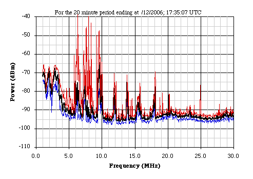
Fig. A1-a
Natural RF Radiant
Energy Spectra of Ionosphere
For 20 minute period
The natural RF energy in the ionosphere pumps the resonance and no artificial energy is required to maintain the resonant energy flow. It is recognized that for every energy application system, a source and sink system must exist for the transformation of the potential energy into the desired form of useful work. A heat engine will not function unless there is a heat sink available. A hydro plant will not operate unless there is a lower level sink to accept the flow. For this RF Ionospheric system there must be a reflector, a receiving antenna and the all important sink (matched impedance resistive load). The reflection function would normally be shared between a ground plane and a tuned antenna.
The referenced work by others, shows that 50 kilowatts of electrical energy has been successfully extracted from the resonant flow with no apparent reduction of signal strength. The primary radiation causing ionization of the ionosphere is thought to be ultraviolet solar radiation. Yet the process does not need direct solar radiation to maintain the energy flow and has been shown to operate through the night. It is well known that the Ionospheric layers change in the night shadow. It is fortunate for this process that the ionosphere persists through the night.
Cosmic and terrestrial radiation may contribute energy to the ionization process. A geo perspective of the resonant energy available includes more than just a local vertically reflecting ionosphere and antenna system. The two conducting spheres, the earth-sphere and the ionosphere, must be involved, acting as a resonant waveguide with the atmosphere as an insulating medium. It is not yet known what factors may limit the usable energy available from this process, other than radio interference, aviation safety and public safety.
< Prev Pg Contents Top /\ Bottom \/ >
Sec. 101
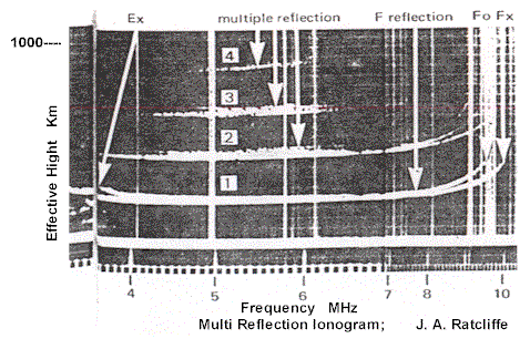
From the ionogram, it is seen that the effective height indicated is 250 km, is 155 miles, is 820 K feet. This is of course deduced from the timing of the echo and where the velocity is taken as 300,000 km/sec. The first echo must have taken 1.66 milli-seconds for a round trip. The three subsequent echoes would be the second, third and fourth multiples of the 1.66 ms time. The one directional trip timing would be 0.833 ms , corresponding to a height of 250 km. The number of wavelengths between reflectors is found to be 4,580 from the frequency of 5.5 megahertz for 0.833 ms.
It is not evident if the dominant 5.5 megahertz resonance frequency is determined by the conditions of the ionosphere or the antenna system. My limited search of ionograms reveal that a large percentage contain multiple reflections. It is assumed that a normal ionosounding installation would not be specifically designed with a highly resonant and reflective antenna system. Multiple reflections can interfere with the desired data. With a proper resonant reflecting antenna system, it is possible to establish continuous resonance and extract useful power from the ionosphere.
It seems logical to expect that any Earth--Ionosphere resonance will only occur at a frequency below the existing MUF (maximum usable frequency). Energy frequencies above the MUF pass through the Ionosphere and are lost to space. The frequencies below the MUF are trapped (reflected) within the space between the ionosphere and Earth and are known to propagate very long distances with multiple skips (echoes ? ). These multiple skips are a close example of the continuous RF resonance that we wish to establish at one location. in order to obtain energy.
The following RF information is from an ARRL http://bplinterference.wikispaces.com/ web discussion concerning the argument that BPL (Broadband Power Line ) internet transmission will degrade shortwave radio use.
Quote from A Good's works :
Q: Isn't long distance HF communications more an infrequent anomaly rather than a common occurrence?
Ans: HF propagation in an area varies on the time of day and on solar activity. It's usually possible to communicate on some HF band to various places in the world 24 hours a day. During the day, the D, E, and F layers form a thicker layer of ionization. This thicker layer absorbs lower frequencies (below 5 Mhz or so), and enables farther propagation of frequencies between 15 and 30 Mhz. At night, the D, E, and F layers combine. This causes the upper frequency limit (called Maximum Usable Frequency or MUF) to drop, usually to about 14 or 15 Mhz. During this time, frequencies below 5 Mhz will propagate better. This is why you can hear many AM broadcast radio stations at night, and most AM radio stations decrease their power at night to avoid interference
Q: Why doesn't my 802.11 WiFi or cellular phone radio signal travel around the world?
Ans: 802.11 WiFi uses 2.4 Ghz frequencies (2400 Mhz) which is considered microwave frequencies, cellular is 800 Mhz, and PCS is around 1.3 Ghz. These do not bounce off of the ionosphere, but travel right through it. The reflective characteristics of the ionosphere diminish above about 30 Mhz. Also, microwave frequencies are much more susceptible to absorption by precipitation and water vapor.
Unquote
< Prev Pg Contents Top /\ Bottom \/ >
Sec. 101
The second major demonstration of this RF energy process
is from the work of Dr. T Henry Moray. The book, The Sea of
Energy 5th edition by Mr. John Moray, documents experiments
where his father, Dr. Moray, obtained up to 50 KW from a
simple long wire antenna and his still secret detecting
equipment. He was able to power lights, heaters, and
specially designed motors. The book gives more than enough
documentation and description to erase any doubts about its
reality.
The book was available from ,
Cosray Research Institute,
2505 South 4th East, Salt Lake City, Utah 84155.
This author
has no association with Moray interests. This knowledge of
their work has been taken solely from the book.
Dr. Moray first started experimenting with obtaining energy from an antenna in 1909 when work with crystal radios was popular. He was able to light a 16 candle power carbon arc light at half power with an antenna and ground. From antenna experience it is known that a one quarter wavelength horizontal antenna that is one sixth of a wavelength above a reflecting surface reflects its dominant energy in the vertical direction. Assuming a resonance at 5 mega hertz, the wavelength is about 200 ft. Therefore if Dr. Moray had used a 50 ft. horizontal wire about 33 ft. above the conductive water table he would have had all of the requirements to establish resonance with the ionosphere. The ground in the Salt Lake valley is highly salty, and conductive and therefore is a good reflector. Cosmic or atmospheric noise pulses have been seen by this author to establish echoes off of the ionosphere and may have initialized the resonance for Dr. Moray. Dr. Moray continued his dedicated research into the 1940's.
Even though he was able to extract 50 KW, [67hp] from his
devices, he was not able to obtain a patent. The patent
office reasoning for denying the patent, as stated by the
book, was
"No natural source of electric wave energy
is known to the Examiner and proof of the existence of such
a source is required."
There is no indication in the book that Dr. Moray ever believed that his system was resonating with the ionosphere. He apparently believed that the energy was being taken from the cosmic background radiation and the disassociation of matter. The antenna systems revealed in the book show no evidence of being designed for a specific frequency or for vertical reception and reflection. The Moray book indicates their energy system consisted of two sections. The first section being an antenna, a resonant circuit, a ground, and a switch to the second section. The second section contained a rectifying detector, ion tubes and transformers forming sub-harmonic resonant circuits to transform the energy to a frequency and voltage compatible with the loads.
Quote: From page 31 of his book, "When his device was set up, he could connect it to an antenna and a ground, and by PRIMING it first and then TUNING it as he primed it, the device would draw electrical energy. This high frequency electric energy produced up to 250,000 volts and it lighted a brighter light than witnesses had ever before seen. Heavy loads could be connected to the device without dimming the lights that were already connected to it. This device worked many miles from any known source of electrical energy, such as transmission lines or radio. The device produced up to 50 kw of power and worked for long periods of time."
Unquote
PRIMING the device consisted of stroking the iron core in
the resonant circuit with a strong magnet. The stroking and
TUNING of the resonant circuit continued as long as 5 to 10
minutes, "then" the switch was closed and the
lights obtained power. When the antenna or ground wire was
momentarily opened and closed the lights would go out and
then return, if the re-closure was soon enough. If
there was a delay before the re-closure, the lights would not
come back on without re-priming.
It seems clear that the priming and
tuning was establishing resonance with the ionosphere. The
priming would furnish the energy for the first reflections,
and the tuning was adjusting the antenna and tank circuit to
a frequency compatible with the ionosphere and the
reflective antenna/ground system.
The book places proprietary and technical importance on the detector, tubes and circuits used to capture the cosmic energy and reduce the frequency to a usable level. Yet, on page 48 is a paragraph that indicates the detector and complex sub-harmonic circuits are not necessary.
Quote: "Dr. Moray made one demonstration not mentioned above to a writer while he only was present. It consisted of lighting a 100 watt globe from CONNECTIONS WITH THE ANTENNA only. It was noted that while this light was burning the lights inside the trunk burned dimly and then assumed their usual brightness when the other lights were taken off. "
Unquote
< Prev Pg Contents Top /\ Bottom \/ >
There is no clear reason why exotic proprietary detectors and ion tubes should be necessary to extract usable energy. A simple non-inductive load resistor matched to the antenna should produce heat. Moray's original antenna experiments which lit a 16 candle power carbon arc light did not use any proprietary equipment. Fluorescent lamps can be directly excited by these frequencies. Tube type diode rectification may be necessary at high power levels with this frequency range of 2 to 13 megahertz. Industrial induction heating uses these frequencies directly. Radio operators refer to the critical frequency of the ionosphere as the highest frequency that will vertically reflect from the ionosphere.
Radio link operators report that,... as they increase their circuit frequency toward the maximum critical frequency, exceedingly strong reception develops. If the circuit frequency is increased further, the signal penetrates the ionosphere and communication is lost.
This suggests that maximum energy may be available just below the critical frequency. The reports from ham radio operators about the large increase in signal strength when nearing the critical frequency of the ionosphere, prompted this research of this RF energy process.
The works of Nikola Tesla with energy transmission via
antennas may have been close to this process. It appears
that his equipment was operating in the kilohertz region.
This resonance appears mainly above two megahertz. Below two
megahertz the absorption in the D layer normally inhibits
reflection for the power levels used in radio.
Theory predicts the system should
operate independently of the grounding wire and ground
reflector. If two reflecting antennas were placed in orbit
with an adequate portion of the ionosphere between them , a
resonant flow should be possible. The following experiment
by Dr. Moray shows that the system can operate without a
grounding conductor.
Quote from page 187, circa 1943:
" He put it in the back of the automobile, with a bank of lights as the resistive load, and drove the car with his family from Salt Lake City to Ashton, Idaho, into Wyoming, back to Salt Lake City and to Denver, letting the device operate continually."
The fact that the unit operated and was later restarted in Denver is also significant. Denver is at 5000 ft altitude and does not have the reflective, salty and moist ground found in Salt Lake City. This seems to indicate that the process can be independent of ground conductors and the Salt Lake City ground reflection conditions. A single satellite with a gravity gradient tether antenna may also be able to use the process. Any planet or moon with an ionosphere should provide some form of RF resonant energy. Ionosounding from earth satellites is common and shows that the ionosphere will reflect upward. The topside ionogram records have not yet been searched for echoes or reflections.
Continued >> Next Pg >
Web page address URL https://energy-gravity.com/RFenergy_Iono.html
Web site by: sbyers11@comcast.net